 Surfacing
– Welcome to the Ball of Confusion! Surfacing
– Welcome to the Ball of Confusion!
Good Surfacing is all about Organization,
Clarity, and Memory
When faced with the enormous challenge
of learning to create complex Pro/Engineer models using surfaces,
the biggest challenge is not figuring out how to create features
– you can look that up in any manual or online tutorial. The
biggest challenges are being able to plan, visualize, and keep track
of what is going on.
Why?
- With solid modeling, its reasonably
clear what you’re doing. You extrude a boss – you
see the boss. You make a hole – you see the hole. Since
you can’t put solid features on Layers, its 100% WYSIWYG
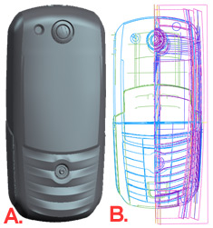
- What You See Is What You Get. Because most of the time, during
the building process, a model that ends up looking like the Motorola
E1000 phone above, Fig.A, will look like the mess that is Fig.
B. Its most definetely not “what you see is what you get”.
Even with a very compact, well-organized model, it can be difficult
to clearly see what’s happening until the last few features.
If you unblank all layers, its totally impossible to figure out
what’s going on because your screen is now one big birds
nest of purple and magenta.
- Asynchronicity – Because
a feature’s references are frequently asynchronous. With
surfaces, you frequently need to go back in time (in the model
tree) to pick up references. Generally, you will have larger,
cleaner surfaces available for use earlier in the model build.
Because these references are not related to other features around
them,
- Because, frequently you end
up modeling negative space for boolean merges. ie. Creating the
shape of a feature you want to make a cut with.
So, what is the best
way to manage the confusion?
Well, my high school Latin teacher,
Aubs, said something that stuck with me forever, and, don’t
worry, it wasn’t about Latin. He said that in order to memorize
the dry, dead language of the past that is Latin, we should do
whatever we need to in order to make it memorable. So he suggested
we should use highlighter or stickers, or lots of different colours,
or arrows, or doodles. Whatever we need to do in order to make
the words personable and signify something to us.
This approach works just as well
for Pro/Engineer as it does for Latin. And it is especially useful
for complex surfacing.
So…
- Create a layering scheme
that makes sense to you – and use it! Create friendly
and simple layer names and and automate the placement of features
onto those layers where possible. For example, I always have a
Surface Layer and a Curve Layer where objects are automatically
placed. Additionally, I manually place parting surfaces on a Parting
Layer and construction surfaces on a Construction Layer. Then,
functional features are placed on appropriate layers: there will
be a Front Housing layer, a Cooling Fan layer, a Battery layer,
etc. This makes it extremely easy to only show those items on
the screen that are relevant to what you are working on.
- Minimize feature
count – the fewer
features you have, the fewer you have to remember! Believe me,
you’ll appreciate this as you get older and your memory
turns to mush! However, there are many other benefits to low feature
count: fewer surface patches create better relationships with
child features; a small model is generally a well organised (keeping
it small forces you to think about structure); small models regenerate
faster.
- Colour your features
– surfaces and datum curves can be coloured although surface
colour is only visible in shaded mode. This works well for standalone
models. Beware that coloured surface features will propogate this
colour through an external merge to the target parts when using
the Master Model technique. This can be annoying. At this stage,
I normally remove colour from all objects in the Master at that
stage.
- Name your features
in the model tree to provide clarity. This is mainly
for your benefit, but it may be extremely useful for downstream
users and the poor sod that has to tweak your model while you’re
off on your holidays. Another major benefit becomes apparent if
you ever need to hand-off your model to a remote location. Named
features become street signs when walking another user through
your model on the phone. For example, you may have many offsets
in your data. Wouldn’t it be nice if the main offset for
the core side geometry were named “Main-Offset-Core”
or something similar, rather than “Feature 121”? You
will now find yourself describing other features with respect
to this named feature.
- Create surface
merges as soon as possible after surface creation.
This does two things for you. It immediately reduces the number
of quilts by one, and it associates the merge with the surface
through its relative position.
- Put features in a meaningful
order and group them appropriately. Groups aren’t
just for bosses with on-the-fly datums. Use groups to slice up
the model tree into nice logical chunks. Although they don’t
reduce feature count, they do reduce apparent feature count and
improve organization. Its quite nice to open a part and find most
of the features grouped in a functional mode similar to the layer
scheme described above. For example, in a 200 feature model, there
might be 7 or 8 groups of features named, Base-Curves, Base-Surfaces,
Front-Housing, Rear-Housing, Battery-Door, etc.
- Split out complexity
– go to master or copy geom – multiple levels ie.
If you have 300 features and you have a main surface quilt plus
secondary details, you could create a simple model that only contains
the initial datum curves and primary enclosure quilt (pic example).
Then merge (or copy geom) this part into the secondary model.
This does’t reduce feature count – the total will
still be the same – but it does simplify the model. You
may now have one initial model with 100 features, and a secondary
model with 200 features.
In a perfect world, you would
be able to model blind. Well almost blind. Immagine being able
to look at the model tree and not the geometry and being able
to see the product grow from feature to feature. What does it
take to do this? You just need to implement the suggestions
above and be very consistent with the order and way you build
features. If you do that, your model tree will communicate information
to you in this kind of way...
- Surface B follows Datum curve
A, so it probably is a child
- Surface Merge C follows Surface
B, so it must be related
- Features A through F are grouped
together and labeled "Handle" so they must form the
handle of the product.
- Copy Surface X is named in such
a way that I know that this is where I copy the outer surface
to close the quilt for the handle which is going to happen in
the next group of features.
Do you remember the film, the
matrix? If the Tank character can look at a stream of numbers
and letters on the screen and interprete these into people and
cityscapes, then you shouldn’t have any problem at all
with relatively simple 3D geometry.
|